
Date:2025-06-24 Views:1006
Table of contents
Powder Metallurgy Parts in Household Appliances
Powder Metallurgy Parts in Automatic Washing Machines
Powder Metallurgy Parts in Electric Fans
Powder Metallurgy Parts in Refrigeration Compressors
Household appliances, by definition, are electrical devices closely related to daily home life, such as refrigerators, air conditioners, electric fans, exhaust fans, washing machines, vacuum cleaners, food processors, electric shavers, hair dryers, massagers, tape recorders, video recorders, and audio systems. The most widely used and indispensable powder metallurgy part in household appliances is the sintered oil-impregnated bearing. For more detailed information on the production, performance, and applications of sintered oil-impregnated bearings, please refer to relevant specialized works. In this chapter, only a brief introduction will be given on the powder metallurgy structural parts used in several representative products, such as washing machines, refrigeration compressors in household refrigerators, and electric fans.
The fully automatic washing machines currently available on the market are broadly categorized into three types: the front-loading drum-type washing machine invented in Europe, the top-loading agitator-type washing machine invented in Asia, and the "agitator" washing machine invented in North America.
As early as the early 1970s, General Electric in the United States replaced two machined steel components in the transmission of the "agitator" automatic washing machine (Figure 7-1) with newly designed powder metallurgy parts. These two parts are the locking tube and the spinning tube, as shown in Figure 7-2.
Figure 7-3 illustrates the machined design and powder metallurgy design of the spinning tube and locking tube. It can be seen from Figure 7-3 that the machined spinning tube is an assembly, consisting of a machined steel tube and two sintered oil-impregnated bearings pressed at both ends. The newly designed powder metallurgy spinning tube is a single part, with a reduced total wall thickness at the lower end, but it still has sufficient practical strength and is easy to manufacture.
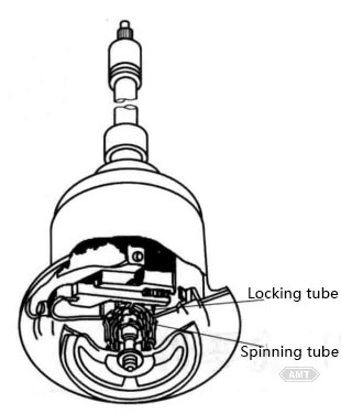
Figure 7-1 Transmission of an Automatic Washing Machine
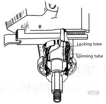
Figure 7-2 Arrangement of Locking Tube and Spinning Tube
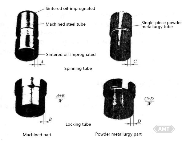
Figure 7-3 Machined and Powder Metallurgy Designs of Spinning Tube and Locking Tube
The single-piece powder metallurgy spinning tube is made of powder metallurgy steel F-0008-20, with a density of 5.9 to 6.1 g/cm3. This density of powder metallurgy steel has sufficient structural strength, and its density is low enough to allow the lubricating oil to be wicked to the interface between the shaft and the bearing. The inherent characteristics of the powder metallurgy process produce parts with the required dimensions and surface roughness precision for the bearing surface, while also providing appropriate structural support strength for the drive shaft and locking tube. The only subsequent machining required is to cut a small chamfer on the large outer diameter to "guide" the assembly of the pressed components.
The powder metallurgy locking tube is made of powder metallurgy copper steel FC-0205-40, with a material density of 6.8 to 7.2 g/cm3. The addition of copper and the higher density are intended to provide sufficient impact strength in the cutout area and wear resistance for the spring clutch. The characteristics of the powder metallurgy process include precise dimensional tolerances, flat part surfaces, and the ability to press-form flange cutouts without subsequent machining.
The redesigned powder metallurgy parts have reduced production costs related to labor, management, and scrap loss, with annual savings exceeding $250,000. The design of powder metallurgy parts is relatively "loose," allowing for larger dimensional tolerances, which can significantly and comprehensively improve the quality level of the transmission.
Additionally, sintered oil-impregnated bearings are commonly used in washing machine motors. Table 7-1 presents the test results for sintered oil-impregnated bearings used in washing machine motors.
Table 7-1 Test Results of Sintered Oil-Impregnated Bearings for Washing Machine Motors
Item | Starting Voltage (V) | Temperature Rise (℃) | Noise (dB) | Vibration (mm) | Sleeve Wear (mm) | Shaft Wear (mm) | Clearance (mm) |
Before Test | 23.8 | Room Temperature 30℃ | 35 | Longitudinal: 0.01 Lateral: 0.005 | 0.027 0.023 | ||
After Test | 27.8 | 46.0 | 35.5 | Longitudinal: 0.01 Lateral: 0.005 | 0.009 0.003 | 0.002 0.001 | 0.038 0.028 |
Note: The test running time was 3000 hours; the frequency was 50 Hz/s; the values are the average of 5 units. The test method was the same as the normal washing state, with the rotation direction changed every 30 seconds. In the wear and clearance columns, the upper cell is for the belt pulley side, and the lower cell is for the non-belt pulley side.
Figure 7-4 shows a transmission part for a washing machine registered on the website of the European Powder Metallurgy Association (EPMA) in 2009. This part is a cost-saving powder metallurgy part for washing machine transmissions.
Electric fans are one of the most widely used household appliances, with China's annual production reaching tens of millions. The most critical part in an electric fan is the sintered oil-impregnated bearing.
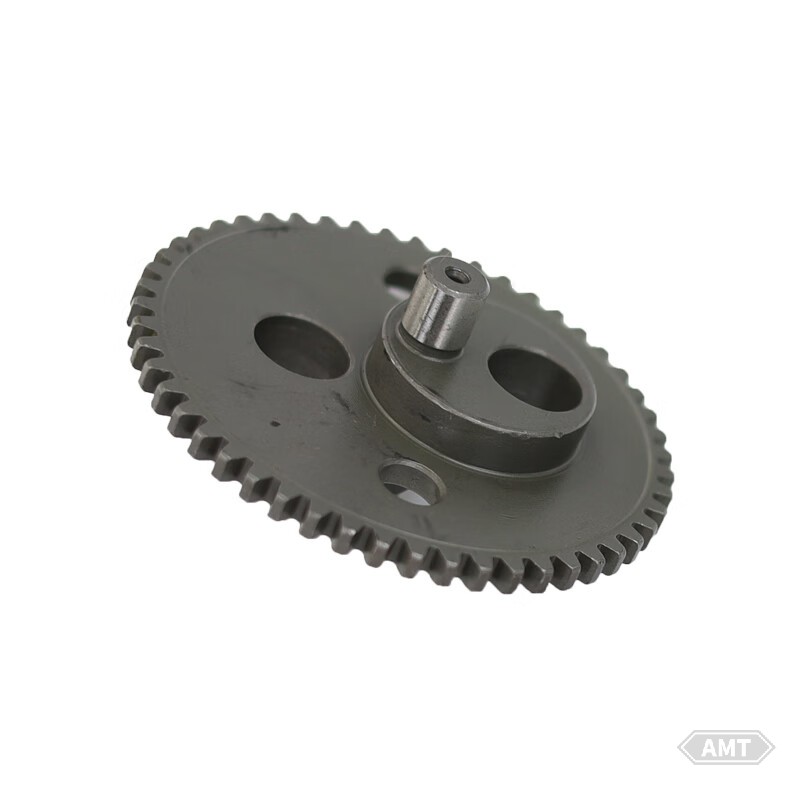
Figure 7-4 Eccentric Gear
The requirements for the sleeve in an electric fan are self-lubrication, low friction, good wear resistance, and low cost.
According to the durability test results of electric fans, the service life exceeds 30,000 hours without additional lubricant replenishment. The operational characteristics such as starting voltage, current, and temperature rise remain normal, and the wear on the sleeve and shaft is minimal. The sintered oil-impregnated bearings used in electric fans are shown in Figure 7-5.
To ensure a long service life for the oil-impregnated bearings, the most critical factors are the type of lubricating oil used and the retention of the impregnated lubricating oil. For the former, turbine oil with high oxidation stability and corrosion resistance, and additives is suitable; for the latter, as shown in Figure 7-6, the oil felt is brought into contact with the outer periphery or end face of the sintered bearing. The lubricating oil is supplied to the interior of the bearing through capillary action, and the lubricating oil that leaks from the sliding surface of the bearing is effectively recovered and recirculated. Additionally, the dust-proof structure of the bearing section is also effective in extending the service life of the bearing.
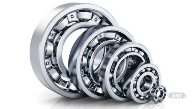
Figure 7-5 Sintered Oil-Impregnated Bearings in Electric Fans
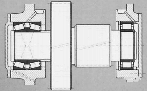
Figure 7-6 Example of Lubricating Oil Supply for Sintered Bearings
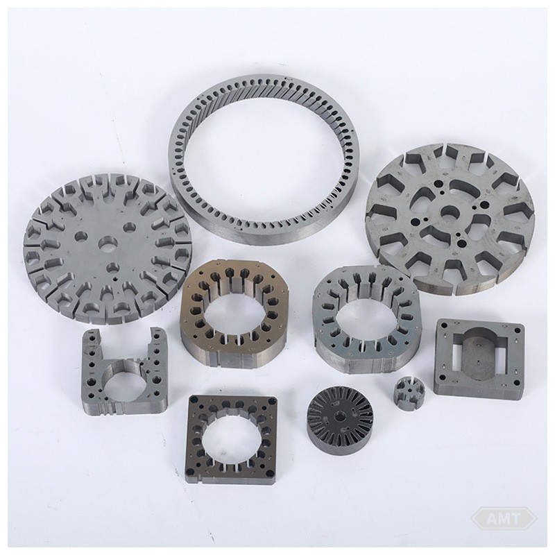
Figure 7-7 Powder Metallurgy Parts in the Oscillating Mechanism of Electric Fans
For household appliance parts, the requirements for material strength are not high, and most are light-load parts. Sintered materials can fully meet the needs. As shown in Figure 7-7, these are the powder metallurgy parts in the oscillating mechanism of electric fans. The upper row in the photo is the crankshaft gear that converts the rotational motion of the motor into reciprocating motion (swinging). The module is 0.5, and the gear precision is JIS5 grade. The bending strength of the sintered gear teeth is 343-441N (including a safety factor). The shaft part in the center hole of the gear needs to be knurled to prevent it from slipping in the gear hole. The meshing surface of the sintered gear is smooth, with minimal initial wear and low noise. The lower right part of Figure 7-7 is a gear-clutch composite part that adjusts the speed and angle of oscillation. This composite part has different numbers of teeth, and a concave recess is designed on one side of the gear's concentric circle, which serves as a mechanism to mesh with the protrusion on the end face of the connecting body. These parts were originally designed as sintered parts, and their shapes are difficult to make with conventional machining. They are examples of parts that fully utilize the characteristics of powder metallurgy.
In the 1990s, China introduced 25 compressor production lines (including refrigerators and room air conditioners) from 20 companies in 8 countries and regions, with an annual production capacity of 14.12 million units. Additionally, two domestic production lines were built, with an annual production capacity of 800,000 units. Based on the structural form of the compressors, in the total annual production capacity (number of units), reciprocating compressors account for 55.4%, rotary compressors for 23.8%, and scroll compressors for 20.8%.
If we say that small refrigeration compressors are the "heart" of refrigerators and room air conditioners, then the quality and service life of this "heart" are determined by powder metallurgy parts.
The production of small refrigeration compressors has a long history in industrially developed countries, but the structural form has not changed much. From the compressor production lines introduced and built in China, reciprocating compressors account for 55.4% of China's total annual production capacity. The main parts used in this type of compressor, such as connecting rods, pistons, valve plates, bearing seats, and end covers, have traditionally been manufactured using cast iron-machining processes.
After entering the 1960s, with the rapid development of powder metallurgy technology, in order to save energy, conserve materials, reduce production costs, and eliminate environmental pollution, compressor manufacturers in the United States, Italy, Japan, and other countries began to replace cast iron-machined parts with powder metallurgy parts. Table 7-2 shows the technical performance of powder metallurgy parts for reciprocating compressors produced by Merisinter in Italy. The powder metallurgy parts used by Zanussi and Niki, two Italian reciprocating compressor manufacturers, are supplied by this company.
Table 7-2 Technical Performance of Powder Metallurgy Parts for Reciprocating Compressors by Merisinter, Italy
Part Name | Mass (g) | Density (g/cm3) | Subsequent Treatment | Performance Requirements |
Connecting Rod | 17.7 | 6.9 | Steam Treatment | High dimensional accuracy, good wear resistance |
Piston | 23.8 | ≥6.5 | Steam Treatment | Gas tightness, good machinability |
Sleeve | 13.9 | 7.0 | Steam Treatment | Improved dimensional accuracy, good wear resistance |
Valve Plate | 4.6 | ≥6.9 | Steam Treatment | Gas tightness, high flatness accuracy |
Based on the analysis of the reciprocating compressor parts from White in the United States, their connecting rods, pistons, and sleeves are all powder metallurgy products, and they have all undergone steam treatment. The chemical composition of these parts is Fe-Cu-C, with a density of 7 to 7.2 g/cm3. The apparent hardness values are as follows: piston 100 to 120 HB; connecting rod 70 to 100 HB; sleeve 70 to 100 HB. The microstructure is ferrite and pearlite.
The exhaust valve guide, intake valve guide, and cylinder liner for reciprocating compressors (room air conditioners) are shown in Figures 7-8 to 7-10 and Table 7-3.
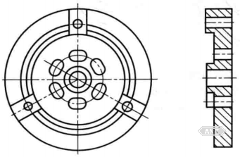
Figure 7-8 Exhaust Valve Guide
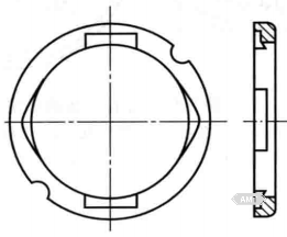
Figure 7-9 Intake Valve Guide
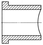
Figure 7-10 Cylinder Liner
Table 7-3 Powder Metallurgy Parts for Reciprocating Compressors in Room Air Conditioners
Part Name | Density (g/cm3) | Material | Required Characteristics |
Exhaust Valve Guide | 6.7 to 7.0 | Fe-1.5Cu-0.4C | Wear resistance |
Intake Valve Guide | 6.7 to 7.0 | Fe-1.5Cu-0.4C | Wear resistance |
Cylinder Liner | 6.2 to 6.6 | Fe-1.5Cu-0.4C | Wear resistance, machinability |
Rotary compressors have a higher coefficient of performance (COP) than reciprocating compressors, are smaller in size, have fewer parts, are lighter in weight, and save 10% to 15% of electricity. Therefore, they are an important category of compressors. As shown in Figure 7-11, the main parts include the upper bearing, lower bearing, cylinder, rotor, and eccentric shaft. Currently, these parts are all produced using the powder metallurgy method. Figure 7-12 shows a schematic diagram of the main parts of a rotary compressor, and Figures 7-13 to 7-16 show the schematic diagrams of each powder metallurgy part.
The core parts of a rotary compressor are the cylinder, rotor, and blade. Their interrelationship is shown in Figure 7-12 The working principle of this compressor is that the electric motor drives the eccentric shaft to rotate. The eccentric shaft causes the rotor to rotate along the inner surface of the cylinder under the end pressure of the blade, thereby compressing the Freon that is drawn in. The blade is pressed against the outer surface of the rotor by a spring.
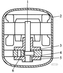
Figure 7-11 Schematic Diagram of a Rotary Compressor
1 - Eccentric Shaft; 2 - Housing; 3 - Upper Bearing; 4 - Cylinder; 5 - Lower Bearing; 6 - Rotor
Table 7-4 Technical Performance of Powder Metallurgy Parts for Rotary Compressors by Sumitomo Electric Industries, Japan
Part Name | Density (g/cm3) | Material | Subsequent Treatment | Required Characteristics |
Upper Bearing | 6.4 to 6.8 | Fe | Steam Treatment | Wear resistance, gas tightness |
Lower Bearing | 6.4 to 6.8 | Fe | Steam Treatment | Wear resistance |
Balance Weight | 6.2 to 6.8 | Fe-1.5Cu-0.4C | Steam Treatment | Weight |
Cylinder | 6.2 to 6.6 | Fe-1.5Cu-0.4C | Steam Treatment | Wear resistance, machinability |
Blade | 6.7 to 7.0 | 61 (copper infiltration material) | Steam Treatment | Wear resistance |
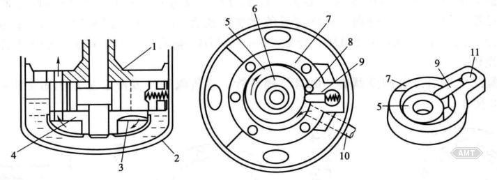
Figure 7-12 Schematic diagram of main components of rotary compressor
1 - Upper Bearing
2 - Housing
3 - Exhaust Valve
4 - Lower Bearing
5 - Rotor
6 - Eccentric Part of the Shaft
7 - Cylinder
8 - Exhaust Port
9 - Blade
10 - Inlet Tube
11 - Blade Slot
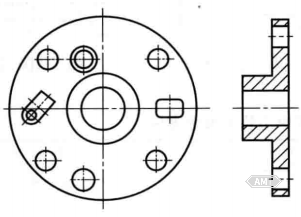
Figure 7-13 Schematic Diagram of the Lower Bearing
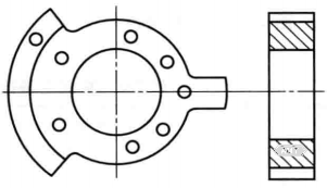
Figure 7-14 Schematic Diagram of the Cylinder
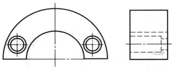
Figure 7-15 Schematic Diagram of the Balance Weight
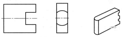
Figure 7-16 Schematic Diagram of the Blade
When the rotor rotates, friction occurs between the rotor and the end of the blade. Due to the harsh lubrication conditions, metal contact is likely to occur. When the blade slides in the blade slot of the cylinder, in addition to the end pressure, the sides are also subjected to lateral pressure, and the lubrication conditions are very poor. Therefore, the blade, rotor, and cylinder must all have excellent wear resistance and be able to adapt to harsh lubrication conditions. Accordingly, the blade is usually made of high-speed steel [Fe-(0.8 to 1.5)C-(3 to 5)Cr-(5 to 20)W-(3 to 10)Mo-(1 to 5)V (sometimes containing Co), mass fraction, the same below] or sintered alloy. Sumitomo Electric Industries in Japan successfully developed a sintered Fe-Cu alloy blade after 10 years of research. This blade needs to be subjected to solid solution treatment to increase its wear resistance. Mitsubishi Metal Corporation in Japan has also developed a sintered alloy for manufacturing blades, with the composition: Fe-(1 to 2)C-(1 to 3)Ni-(4 to 6)Mo. During heat treatment of this alloy, a metal interstitial compound of Fe and Mo is formed and uniformly dispersed in the material, which not only increases the wear resistance of the material but also results in a very small linear expansion coefficient of the material. The wear resistance of this sintered alloy is twice that of ordinary high-speed steel or special cast iron, thereby reducing the wear of the cylinder and increasing the service life of the compressor.
The rotor and blade are a pair of friction pairs with very harsh friction conditions. The rotor can be made of Ni-Cr-Mo steel or Ni-Cr-Mo cast iron or steel and cast iron containing B or heat-treated malleable cast iron and vermicular cast iron. Sumitomo Electric Industries in Japan began researching the use of sintered alloys to manufacture rotors in the late 1970s. After entering the 1980s, there were no further reports, but with the current powder metallurgy technology, the manufacture of sintered Ni-Cr-Mo steel is no longer a problem. For example, the sintered alloy produced by Hitachi Powder Metallurgy (Co., Ltd.) for manufacturing rocker arm inserts has the chemical composition: Fe-(1.5 to 3.0)Mo-(7 to 10)Cr-(0.5 to 2)Ni, with a density of 7.6 to 7.9 g/cm3 and hardness of 50 to 60 HRC.
The cylinder can be made of cast iron or sintered alloy. For a cylinder made of sintered Fe-C alloy, steam treatment must be carried out to increase its wear resistance. However, after steam treatment, a layer of Fe₃O₄ is formed on both the exposed surface and the internal pore surface of the sintered alloy cylinder. Fe₃O₄ has a hardness as high as 50 HRC, so the wear on the sides of the blade sliding in the blade slot of the cylinder may increase. Therefore, when designing the friction pair of the cylinder and blade, it is important to select the appropriate sintered alloy.
In the late 1980s, driven by market demand, some powder metallurgy factories and research institutes in China began to use powder metallurgy methods to develop pistons, connecting rods, and other parts for reciprocating compressors used in refrigerators. After entering the 1990s, the cylinder, upper bearing, and lower bearing of rotary compressors also began to be mass-produced. However, there are still several issues that need further research:
(1) Dimensional Accuracy
Compressor parts require high dimensional accuracy. However, while powder metallurgy parts have high radial dimensional accuracy, their axial dimensional accuracy is relatively poor. Therefore, for parts with high flatness requirements, such as valve plates, surface grinding is necessary. When radial dimensional tolerances are particularly tight, such as the blade sliding slot of the cylinder, machining is required.
Thus, in the powder metallurgy process, how to improve the dimensional accuracy of powder metallurgy parts and maintain the consistency of dimensional accuracy to reduce subsequent machining is an important topic that must be studied.
(2) Machinability
Some powder metallurgy parts require drilling (such as pistons), machining (such as cylinders), and other machining operations. Powder metallurgy materials contain numerous small pores, which cause intermittent cutting during machining, exacerbating tool wear. Therefore, it is necessary to develop easy-to-machine sintered alloys. Currently, to solve the machining problems of compressor parts in China, most of them use 600MS powder produced by Kobe Steel in Japan as the raw powder.
To improve the machinability of iron-based powder metallurgy materials, it is common internationally to add additives such as MnS and BN (hexagonal) to the raw powder. Recently, Hoganas in Sweden has proposed the addition of MnX.
(3) Wear Resistance
One of the basic performance requirements for compressor parts is good wear resistance. This performance is mainly achieved through subsequent treatments such as steam treatment, solid solution treatment, and heat treatment. Among them, steam treatment is widely used. In addition to increasing wear resistance, steam treatment also has a certain pore-sealing effect.
(4) Gas Tightness
Compressor parts such as pistons, valve plates, and cylinders require a special performance: they must not leak gas under certain pressure, that is, they must have good gas tightness. For example, pistons are required to remain gas-tight for at least 3 minutes under a pressure of 1.5 MPa. Although steam treatment has a certain pore-sealing effect, it is not very reliable. According to tests using anaerobic adhesive for pore sealing, the holding time is greater than 3 minutes under a pressure of 2.5 MPa. In recent years, Ultraseal International Limited in the UK has developed an acrylic sealing technology that can seal the entire surface of powder metallurgy parts in one treatment.
(5) New Product Development
Blades and rotors are two key parts in rotary compressors, and there have been no reports on the domestic development of these two powder metallurgy parts to date.
Power tools are mechanized tools driven by an electric motor or electromagnet, which transmit power to the working head through a transmission mechanism. Since the first DC electric drill was manufactured in Germany in 1895, power tools have a history of about 115 years.
Nowadays, the main types of power tools include metal-cutting power tools, grinding power tools, assembly power tools, and railway power tools. Common power tools are electric drills, electric grinding wheels, electric wrenches and screwdrivers, electric hammers and impact drills, concrete vibrators, and electric planers. In 2008, the production volume of power tools in China was approximately 40 million units. Powder metallurgy structural parts have been widely used in power tools. Table 7-5 provides some examples of powder metallurgy parts used in various power tools.
Table 7-5 Examples of Powder Metallurgy Parts in Various Power Tool
| Power Tool Name | Part Name | Material | Features |
|---|---|---|---|
| Hand Drill | Bearings | Cu-Sn, 6.6 to 7.2 g/cm³ | Self-lubricating |
| Bushings | Fe, 5.6 to 6.2 g/cm² | Self-lubricating | |
| Couplings | Fe-2Cu-0.7C, 6.7 to 7.0 g/cm², Hardened by High-Frequency Quenching | Wear resistance (threaded section) | |
| Spur Gears | Fe-2Cu-0.7C, 6.7 to 7.0 g/cm² | Wear resistance | |
| Helical Gears | Fe-2Cu-0.7C, 6.7 to 7.0 g/cm² | Wear resistance | |
| Helical Gears (A) | Fe-2Cu-0.7C, 6.7 to 7.0 g/cm², Embedded in Resin | Wear resistance, Insulation | |
| Nuts | Fe-2Cu-0.7C, 6.8 to 7.1 g/cm³, Carburized and Quenched | Wear resistance | |
| Hammer Drill | Swappers | Fe-1.5Cu-0.4C, 6.2 to 6.6 g/cm, Carburized and Quenched | Wear resistance |
| Ratchets | Fe-2Cu, 7.0 to 7.4 g/cm, Carburized and Quenched | Wear resistance, Ratchet strength | |
| Stopper | Fe-1.5Cu-0.4C, 6.2 to 6.6 g/cm³, Steam Treatment | Self-lubricating | |
| Bushings | Cu-Sn, 6.6 to 7.0 g/cm² | Self-lubricating | |
| Bushings | Fe, 5.6 to 6.2 g/cm² | Self-lubricating | |
| Planer | Bushings | Cu-Sn, 6.6 to 7.2 g/cm² | Self-lubricating |
| Bushings | Fe, 5.6 to 6.2 g/cm | Self-lubricating | |
| Pulley-C | Fe-1.5Cu-0.4C, 6.2 to 6.6 g/cm, Steam Treatment | Wear resistance | |
| Pulley-B | Fe-1.5Cu-0.4C, 6.2 to 6.6 g/cm³, Steam Treatment | Wear resistance | |
| Pulley-A | Fe-1.5Cu-0.4C, 6.2 to 6.6 g/cm², Steam Treatment | Wear resistance | |
| Circular Saw | Washers | Fe-1.5Cu-0.4C, 6.7 to 7.0 g/cm, Steam Treatment | Compressive strength |
| Washers | Fe-2Cu-0.7C, 6.7 to 7.0 g/cm³, Steam Treatment | Compressive strength | |
| Band Saw | Gears | Fe-2Cu-0.7C, 6.7 to 7.0 g/cm³ | Wear resistance |
| Balancing Weight | Fe-2Cu, 7.0 to 7.4 g/cm², Carburized and Quenched | Wear resistance, Weight | |
| Gear Housing | Fe-1.5Cu-0.4C, 6.2 to 6.6 g/cm² | ||
| Bench Drill | Gears | Fe-2Cu-0.7C, 6.7 to 7.0 g/cm² | Wear resistance |
| Helical Gears | Fe-2Cu-0.7C, 6.7 to 7.0 g/cm² | Wear resistance |
In order to achieve the highest efficiency and lowest production costs by using powder metallurgy parts, power tool manufacturers first need to determine the following parameters:
What parts to manufacture?
What are the various functions of these parts?
What are their important mechanical properties?
What are the competing manufacturing processes, and what are their production costs?
The gears used in power tools include spur gears, bevel gears, face gears, pinions, helical bevel gears, gear sets, and ratchets, each with its own specific requirements.
Power tools also use cams, rods, counterweights, bearings, bearing housings, brush holders, clutches, rotors, cylinders, end caps, blades, and collet jaws. To some extent, all of these parts are produced using the powder metallurgy process for different tools. There is a significant difference in the mechanical properties required for these parts. Below are discussions on several representative parts manufactured using the powder metallurgy process and related issues.
The physical and mechanical properties of powder metallurgy structural part materials vary depending on density, sintering conditions, and subsequent treatments. Detailed data can be found in ISO 5755:2001(E) (GB/T 19076-2003) "Specification for Sintered Metallic Materials" and MPIF Standard 35 "Standard for Powder Metallurgy Structural Parts Materials" (2009 edition). For specific part performance, examples are provided below.
The 6.35 mm hand drill (Figure 7-17) is a commonly used power tool and is worth analyzing in detail.
To manufacture this type of hand drill, it is necessary to first establish some basic design parameters, such as power output, the minimum service life of the drill, and its general price range. Once these basic elements are determined, the next step is to determine the design of the gear system. With the motor fixed at 2.3 A, operating at 22,000 r/min with a power of 0.1865 kW, and a drill bit speed of 2,000 r/min, the actual torque absorbed by each gear tooth can be determined. This must match the strength and hardness of the motor's pinion gear, as well as the required safety factor, providing all the data needed to correctly select the material and density for the gear system. In fact, carbon steel with a density of 6.4 to 6.8 g/cm3 and carbonitrided is capable of withstanding the wear rate required for the design life of this tool. However, this material is neither impact-resistant nor capable of absorbing vibrations caused by impacts on knots, nails, or steel burrs. Using a secondary pressing and secondary sintering process, where this material is refined to increase the density to 7.3 g/cm3 and then sintered again, can solve this problem. However, its production cost is much higher than that of using low-alloy steel powder. Nickel steel and copper steel have strengths and wear resistance suitable for this application and are satisfactory in use. Nickel steel is used in most applications with high impact loads, while copper steel is used in applications with lower vibration loads. In this particular drill, due to the high strength of the design, the main gear is designed as a helical gear. The other two gears are designed as spur gears. The materials used are FN-0205-25 and FN-0205-30 from MPIF Standard 35 (with densities of 6.9 to 7.2 g/cm3). As shown in Figure 7-18, the helical gear must reach AGMA Grade 6, while the other two spur gears must reach AGMA Grade 8.
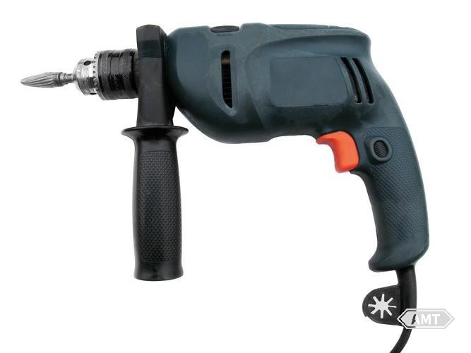
Figure 7-17 6.35 mm Hand Drill
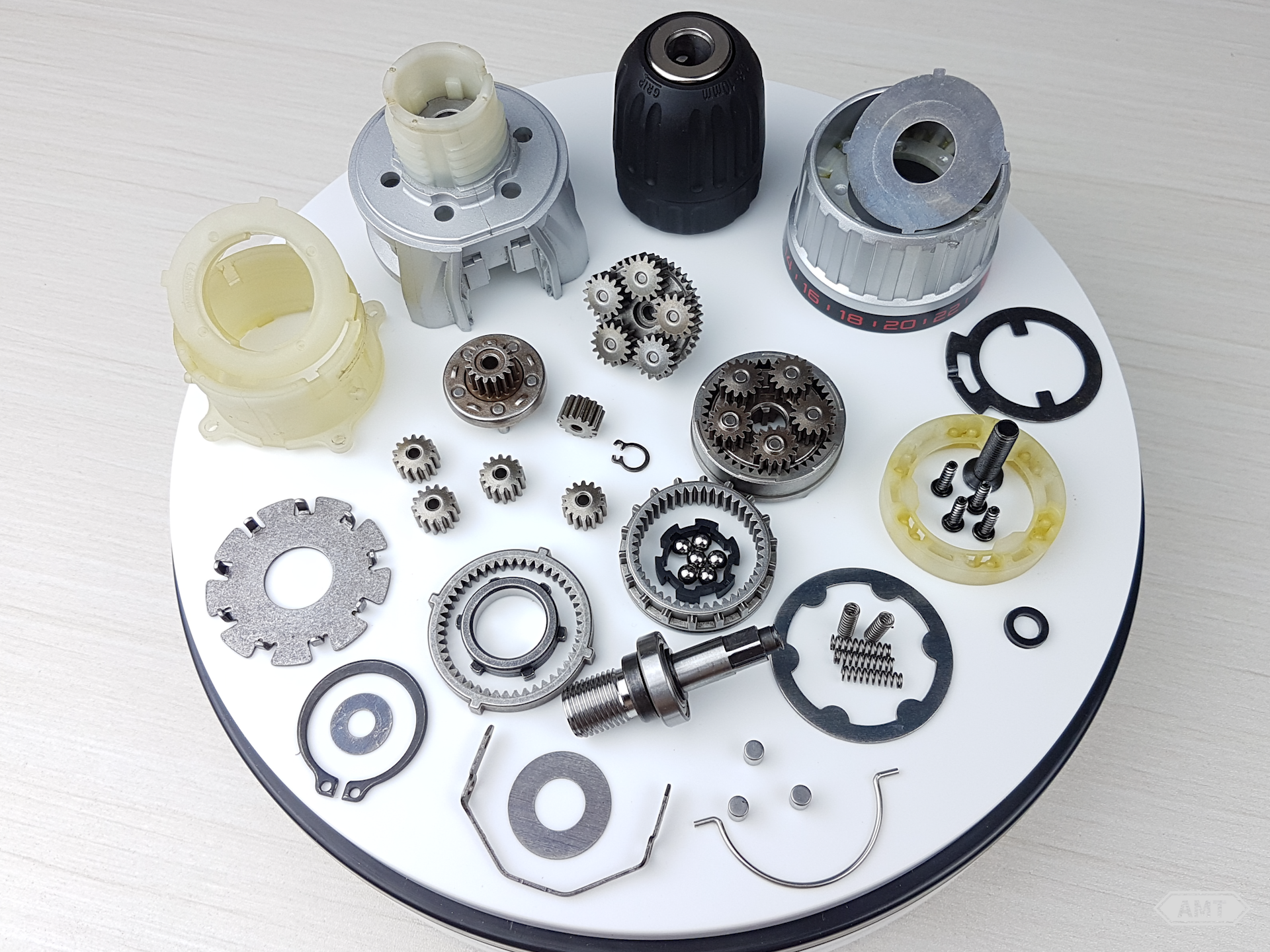
Figure 7-18 Powder Metallurgy Parts in a Hand Drill
The hardness of the gears is crucial. The hardness range for the helical gear is 25 to 35 HRC, while the hardness range for the other two gears is 30 to 38 HRC. If the gear hardness is too high, it will wear out the small gear on the shaft; if the gear hardness is too low, it will wear out faster itself.
All gears are inspected after sintering. All gears are treated with oil immersion before assembly. Powder metallurgy gears save approximately 45% of the cost compared to machined gears.
Below are several examples of powder metallurgy parts.
The ratchet assembly consists of a hub, flange, and ratchet, which were originally produced from forgings. After being converted to powder metallurgy parts, the production cost was reduced by 30%. The density of the powder metallurgy flange and ratchet is 7.1 g/cm3, with a tensile strength of 1000 MPa and a fatigue strength of 379 MPa. The hub has a density of g/cm3, with a tensile strength of 689 MPa and a fatigue strength of 290 MPa.
Figure 7-19 Ratchet Assembly
This gear set (Figure 7-20) is a high-performance special-purpose drilling machine. The gear has a density of 7.2 g/cm3 and a tensile strength of 1100 MPa, with a yield strength (0.2%) of ZHR requiring heat treatment.
Figure 7-20 Gear set for high-performance specialized drilling machines
This is a Cylkro gear set for power tools (Figure 7-21). The part is produced by MiniGear in Italy. The part has a forming density of 7.0 g/cm3 and a tensile strength of 950 MPa. The gear is designed to mesh with a helical pinion at a 90° angle. This is the first example of a helical gear and face gear meshing in powder metallurgy. Using powder metallurgy gears can reduce production costs by 50%.
This is a bevel gear for a large-angle grinding machine (Figure 7-22). The bevel gear has a density of 7.25 to 7.35 g/cm3, a tensile strength of 1138 MPa, and a yield strength of 483 MPa. The part requires heat treatment but is supplied in the final form without the need for subsequent machining, resulting in significant cost savings.
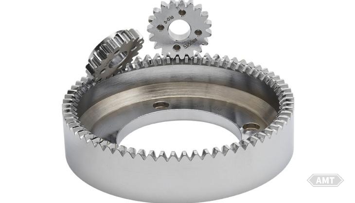
Figure 7-21 Cylkro Gear Set
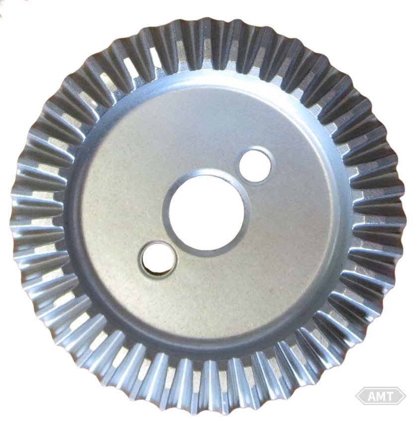
Figure 7-22 Bevel Gear
The reciprocating saw (Figure 7-23) is a tool with harsh working conditions but low cost. This is because its motion changes from rotation to pulsation, generating several vibrations, and both impact and wear loads are quite high. As shown in Figure 7-24, these are the powder metallurgy parts used in the reciprocating saw.
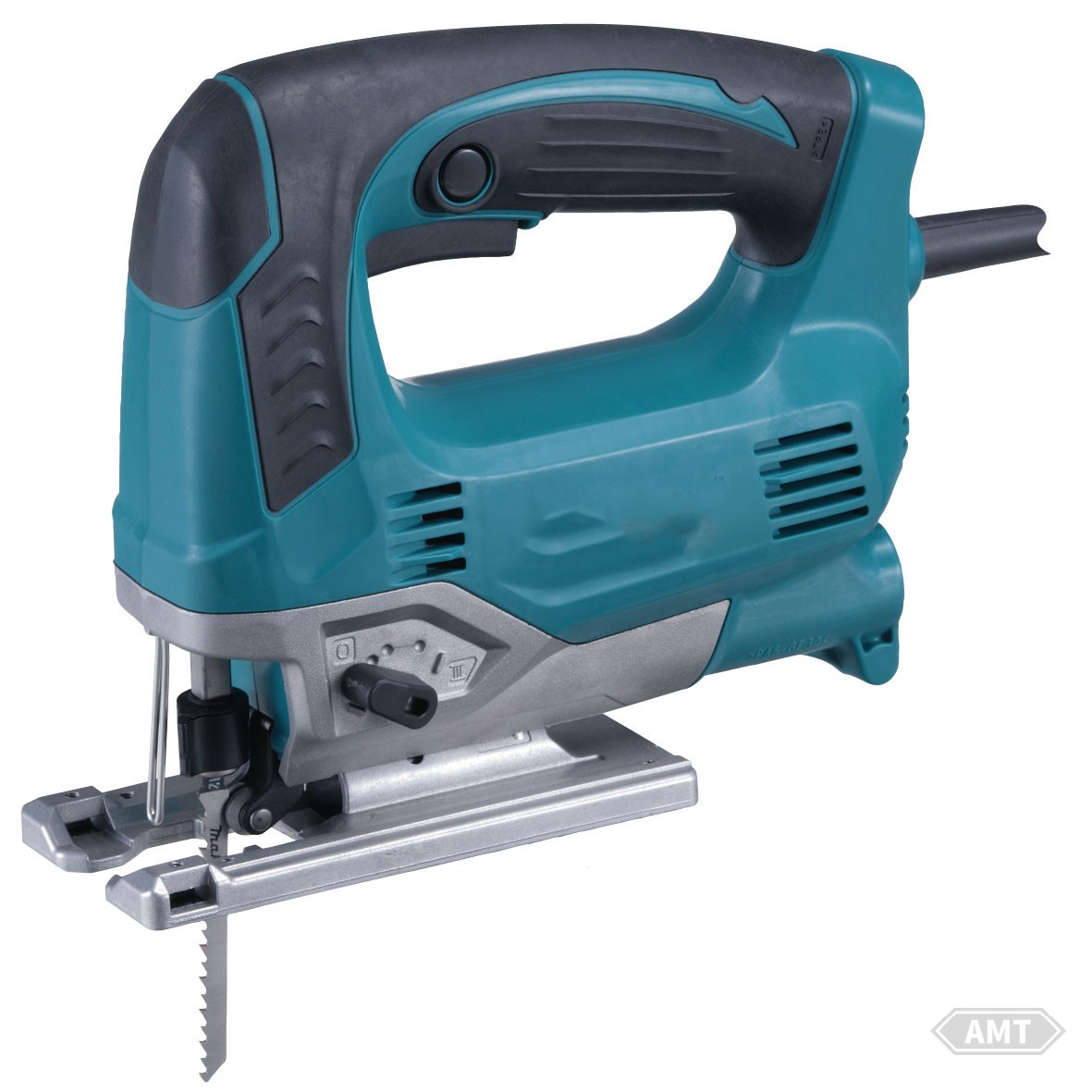
Figure 7-23 Reciprocating Saw
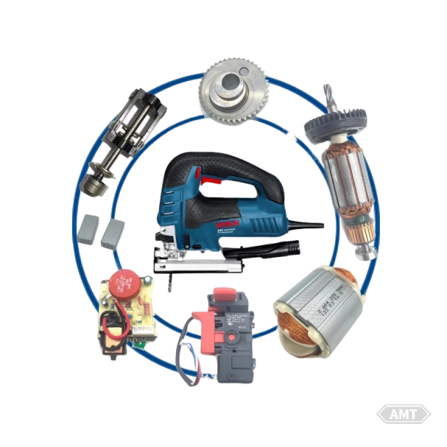
Figure 7-24 Powder Metallurgy Parts in a Reciprocating Saw
In the reciprocating saw, there is only one helical gear with an eccentric cam on one end. Given the high vibration load and wear factors, this gear is designed to be made of copper-infiltrated high-carbon steel with a density of no less than g/cm3. The density balance between the gear and the cam is very important. Additionally, hardness, torque, and strength must meet technical requirements.
The counterweight is made of nickel steel with a density of 6.9 g/cm3 and must be heat-treated to a hardness of 15 to 25 HRC. This part must undergo a transverse rupture test. The life of the reciprocating saw depends on the balance of hardness and strength between the gear cam and the counterweight load surfaces.
The saw blade clamp is also made of nickel steel with a density of no less than g/cm3. Especially when the reciprocating saw begins to cut into internal holes, the clamp experiences a high vibration load. During use, it also withstands bending and torsional stresses. Therefore, the integrity and strength of this part must be carefully inspected, and heat treatment must be strictly controlled to prevent embrittlement.
If all these parts were machined from bar stock, the total cost of the reciprocating saw would be higher than market prices and would not be feasible for production.
Below are several examples of powder metallurgy parts applications.
This assembly is a reciprocating saw assembly (Figure 7-25). These complex-shaped parts are made of diffusion alloyed steel (MPIF material standard FD-0205-120HT). The part density is 6.85 to 6.95 g/cm3, with a minimum ultimate tensile strength of 830 MPa. The special model number for the reciprocating saw is 9543, used for cutting metals, powders, and plastics. Using powder metallurgy parts instead of machined parts can reduce production costs by more than 50%, and eliminate three parts: the eccentric gear, screw, and pin.
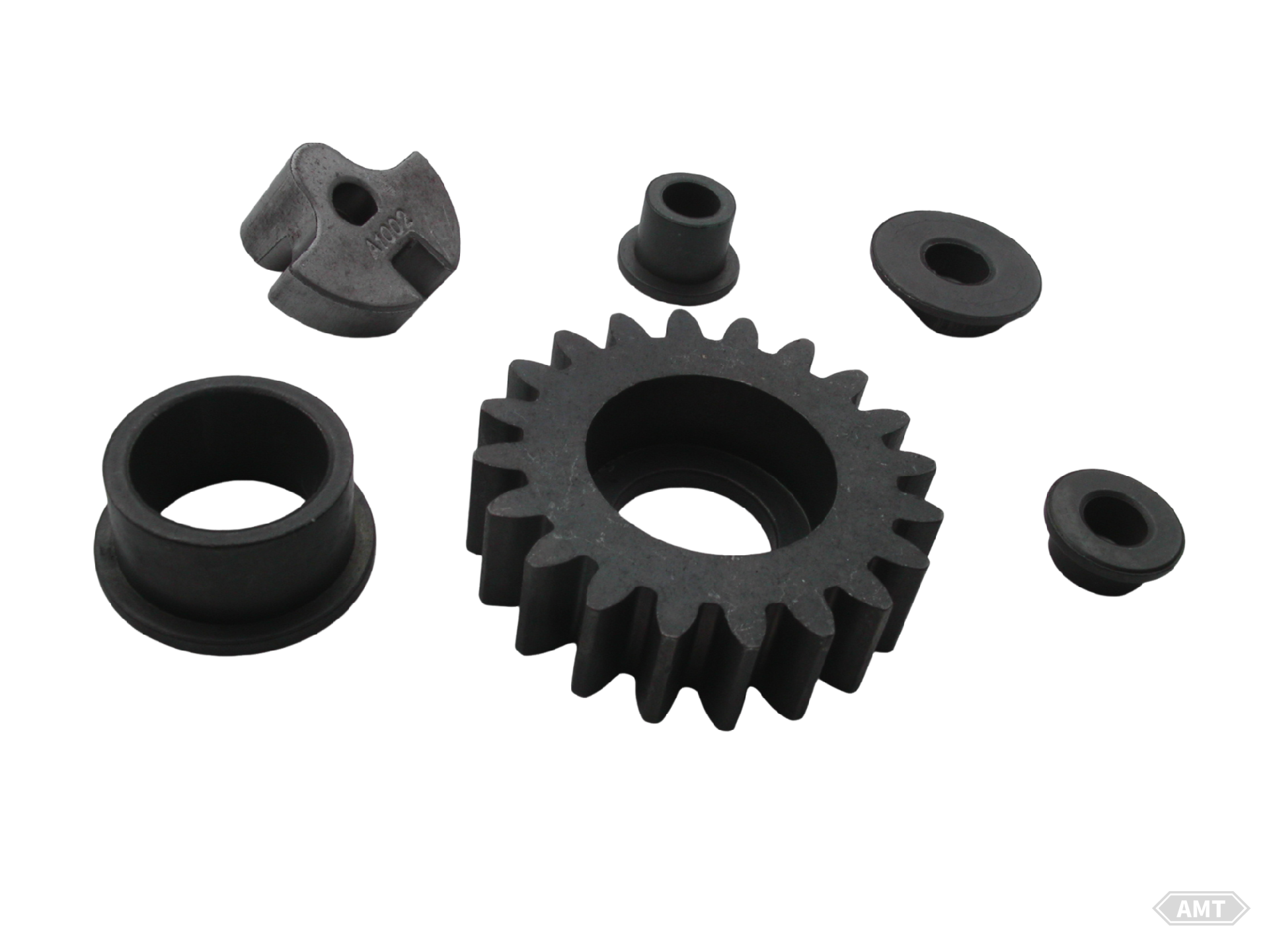
Figure 7-25 Reciprocating Saw Assembly
The density of the reciprocating saw assembly (Figure 7-26) is 6.85 to 6.9 g/cm3. The production process includes sintering, machining, and heat treatment.
This part is a helical bevel gear used in a reciprocating electric saw (Figure 7-27). It is formed using warm pressing with a forming density of 7.2 to 7.3 g/cm3. By selecting the warm pressing process, near-net-shape forging, machining, and gear cutting are eliminated. To increase the eccentric vibration force, two irregular holes are designed in the part.
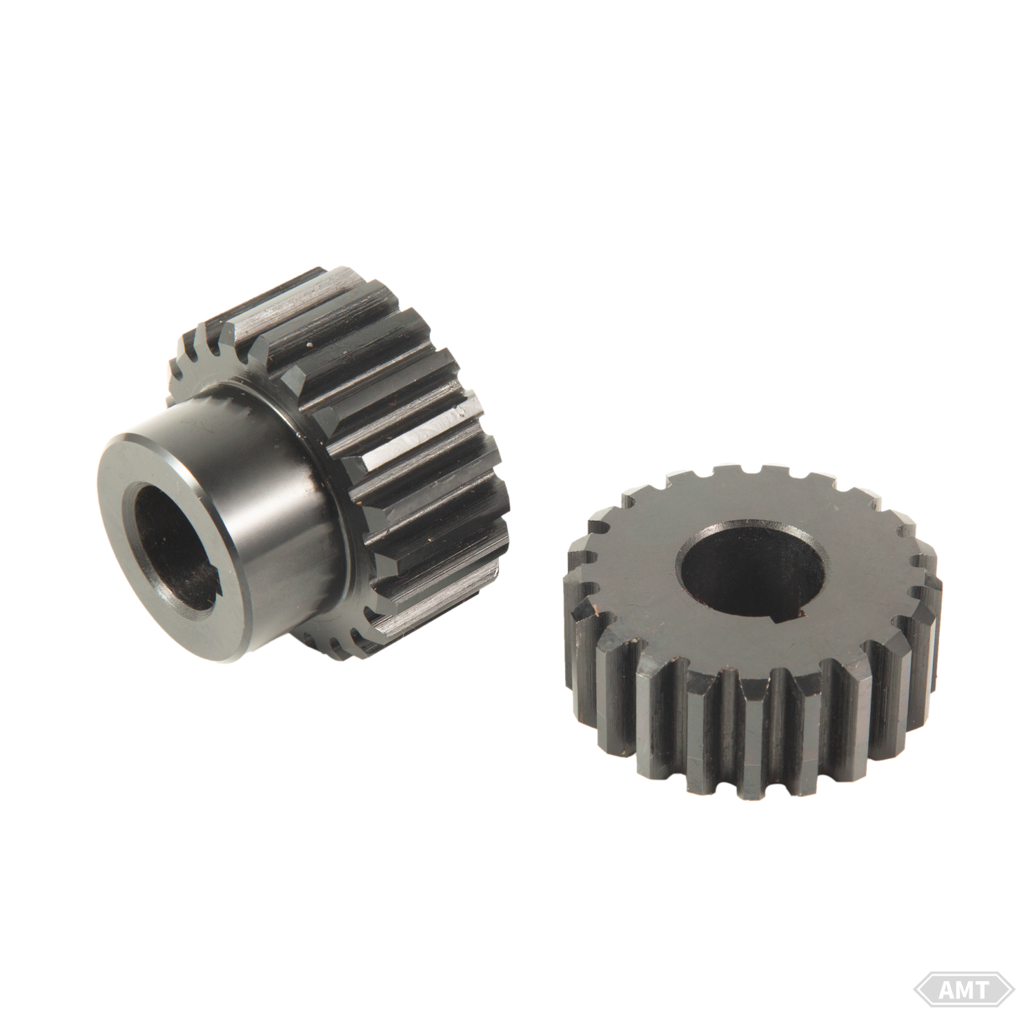
Figure 7-26 Reciprocating Saw Assembly (Spur Gear and Plate)
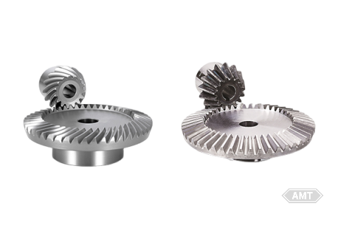
Figure 7-27 Helical Bevel Gear
The helical gear teeth, after sintering and heat treatment, achieve AGMA Grade 7 accuracy. The part has an ultimate tensile strength of 1103 MPa and a hardness of 43 HRC. Compared to alternative manufacturing processes, the powder metallurgy process can reduce production costs by 55%.
This is a low-alloy steel MIM saw blade clamp for the DeWalt DW303MK reciprocating saw. The keyless saw blade clamp secures the saw blade in place, ensuring it is fixed to the power head. This complex final shape part is formed using a multi-cavity injection mold with 4 sliders, 3 cores, and 15 sealing surfaces in each cavity. In fact, this design combines two previous MIM parts into one. Given that it contains 2 moving parts and 1 spring, part accuracy is crucial. The final assembly includes pressing a ground pin through two holes at the end of the part to connect the saw blade clamp to the reciprocating saw shaft. The press fit requires a tolerance of ±0.03 mm for each hole and a minimum CPK (process capability index) of 1.33, which reduces the tolerance to ±0.023 mm. The part has the following properties: ultimate tensile strength of 1655 MPa, yield strength of 1483 MPa, and hardness of 48 to 51 HRC. Using powder metallurgy parts can reduce production costs by 27%, eliminate machining, assembly, and reduce usage failures.
This part is made using the MIM process from 316 stainless steel powder (Cr 16.7%, Ni 13%, Mo 2.3%). The part density is 4.7 g/cm3 in the brown state and 7.75 g/cm3 after sintering. The ultimate tensile strength is 500 MPa, the yield strength (0.2%) is 290 MPa, and the hardness is 170 HV10. This MIM part is used to fix the handheld electric wire saw and connect the saw blade to the vibrating drive unit. To ensure good model filling, two gates were used during forming.
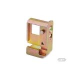
Figure 7-29 Saw Blade Holder
In power tools, the powder metallurgy parts in pruning shears (Figure 7-30) are subjected to the most severe operating conditions. In these tools, rotational motion must be converted into reciprocating motion in both directions. Compared to other tools, the vibration is intense, the load is heavy, the deceleration is much faster, and the tools are often severely misused by household users under harsh vibration loads. Pruning shears are used for trimming branches, hedge trimming, root carving design, and even for cutting barbed wire. In fact, they are sometimes also used for hedge trimming.
As shown in Figure 7-31, these are the powder metallurgy parts used in pruning shears. The main drive gear is made of copper-infiltrated steel with a density of no less than 7.3 g/cm3. The torque of each gear tooth is no less than 61 N·m. The hardness and density of the cam are the same as those of the gear. The saw blade drive arm is made of nickel steel, and its performance is particularly critical. This is because the drive arm must withstand all the vibration from cutting and the full impact when suddenly stopped. These parts must undergo toughness and impact tests before assembly acceptance.
Powder metallurgy bronze oil-impregnated bearings, iron washers, or iron bearing seats, although not high-strength structural parts, each part must undergo at least one mechanical property test, such as transverse rupture strength, radial crushing strength, or cone pin crush test. In addition, for any delivered product, hardness must be inspected during acceptance. In addition to the above mechanical property tests, all parts must undergo routine chemical analysis, and gears must be inspected using a red line recorder against a reference gear.
Figure 7-30 Pruning Shears
Figure 7-31 Powder Metallurgy Parts Used in Pruning Shears
Below is an example of the application of powder metallurgy parts in pruning shears.
The hedge pruning shear gearbox is shown in Figures 7-32. This is a gearbox for a portable hedge pruning shear. The density of the powder metallurgy steel parts is 6.6 to 7.0 g/cm3, with a tensile strength of 510 to 600 MPa. Compared to alternative manufacturing methods, powder metallurgy parts can significantly reduce production costs.
Figure 7-32 Hedge Pruning Shear Gearbox Parts
The parts shown in Figure 7-34 are originally made of 8620 leaded steel and are hardened by carburizing and quenching, with a hardness of 50 to 55 HRC. When converted to powder metallurgy nickel steel with a density of no less than 7.2 g/cm3, the production cost is reduced by about 80%. Before finding a method to increase the density and strength of the ratchet tooth end, wear at the ratchet tooth end has always been a problem, just like with machined gears. The minimum value for the torque test is 67.8 N·m.
The cylinder and piston top of the impact hammer are shown in Figure 7-35. The cylinder is made of nickel steel with a density of no less than g/cm3, while the piston top has a minimum density of 7.0 g/cm3. The piston top still requires further precision machining and tapping, and even in this case, the cost savings compared to machined parts are greater than 70%.
Figure 7-34 Impact Screwdriver Clutch Parts
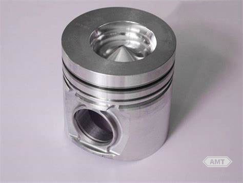
Figure 7-35 Cylinder and Piston Top of Impact Hammer
The radial crushing strength of the cylinder is no less than 13.35 kN, and the strength of the piston top during the "pushing a 5° cone pin through the transverse hole of the drill" test is no less than 4 kN. Both parts require carbonitriding treatment.
Figure 7-37 presents the powder metallurgy compacted pneumatic motor parts. When these four parts are converted to powder metallurgy parts, the actual production cost savings are slightly more than 60%. Due to changes in part design, some milling operations on the housing are eliminated, so the total savings in assembly are actually much greater. These parts do not undergo heat treatment and only require minimal machining before installation. To ensure part integrity, the end cover is subjected to a radial crushing test across the hub, and to ensure that the cylinder and rotor have appropriate strength, these two parts also undergo crushing strength tests.
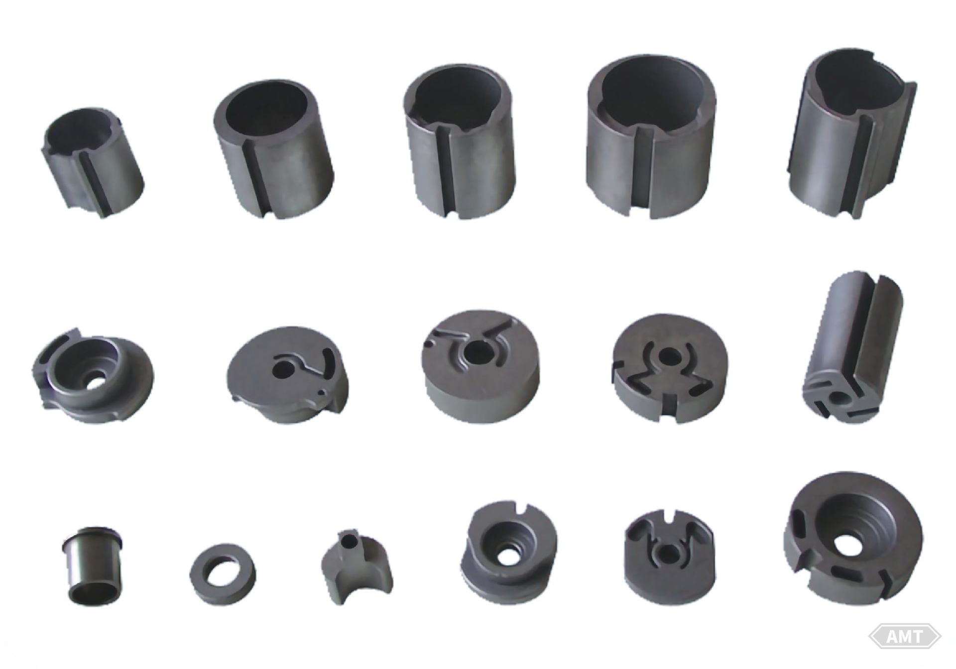
Figure 7-37 Powder Metallurgy Pressed Pneumatic Motor Parts
The application of powder metallurgy structural parts in power tools began in the 1970s. With the rapid development of powder metallurgy technology and materials, high-density, high-strength, and complex-shaped powder metallurgy structural parts are now widely used. The development of powder metallurgy processes has not only provided a way to reduce production costs, conserve materials, and save energy for power tool production but also opened up possibilities for design innovation in power tools.
Leave your email for more ebooks and prices📫 !
Contact:Fidel
Tel:021-5512-8901
Mobile:19916725893
Email:sales7@atmsh.com
Address:No.398 Guiyang Road Yangpu China